Hardware
AUTD3 Device
The AUTD3 device consists of 249 transducers per unit1. Furthermore, multiple devices can be connected and expanded via daisy-chain. From the SDK, the phase/intensity of all these transducers can be individually specified.
The coordinate system of AUTD3 adopts the right-handed coordinate system, with the center of the 0-th transducer as the origin. The x-axis is in the long axis direction, i.e., the direction from 0 to 17, and the y-axis is in the direction from 0 to 18.
Also, the unit of distance is mm. The transducers are arranged at intervals of , and the size including the board is .
Setup
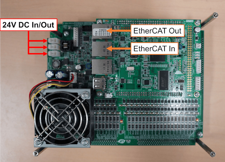
Connect the PC and “EtherCAT In” of the first device with an ethernet cable (CAT 5e or higher), and connect “EtherCAT Out” of the -th device to “EtherCAT In” of the -th device.
The power supply for AUTD3 uses a DC. The power supply can be connected mutually, and any of the three power connectors can be used. The power connector on the AUTD3 device side uses Molex 5566-02A.
NOTE: AUTD3 consumes a maximum of per device. Pay attention to the maximum output current of the power supply.
Dimension Diagram
-
Out of , 3 transducers are removed for screws. The reason for placing the screw holes in this position is to minimize the gap when multiple units are lined up. ↩