GPIO Pins
An AUTD3 device has 4 GPIO input terminals and 4 GPIO output terminals. The locations of the terminals are shown in the figure below.
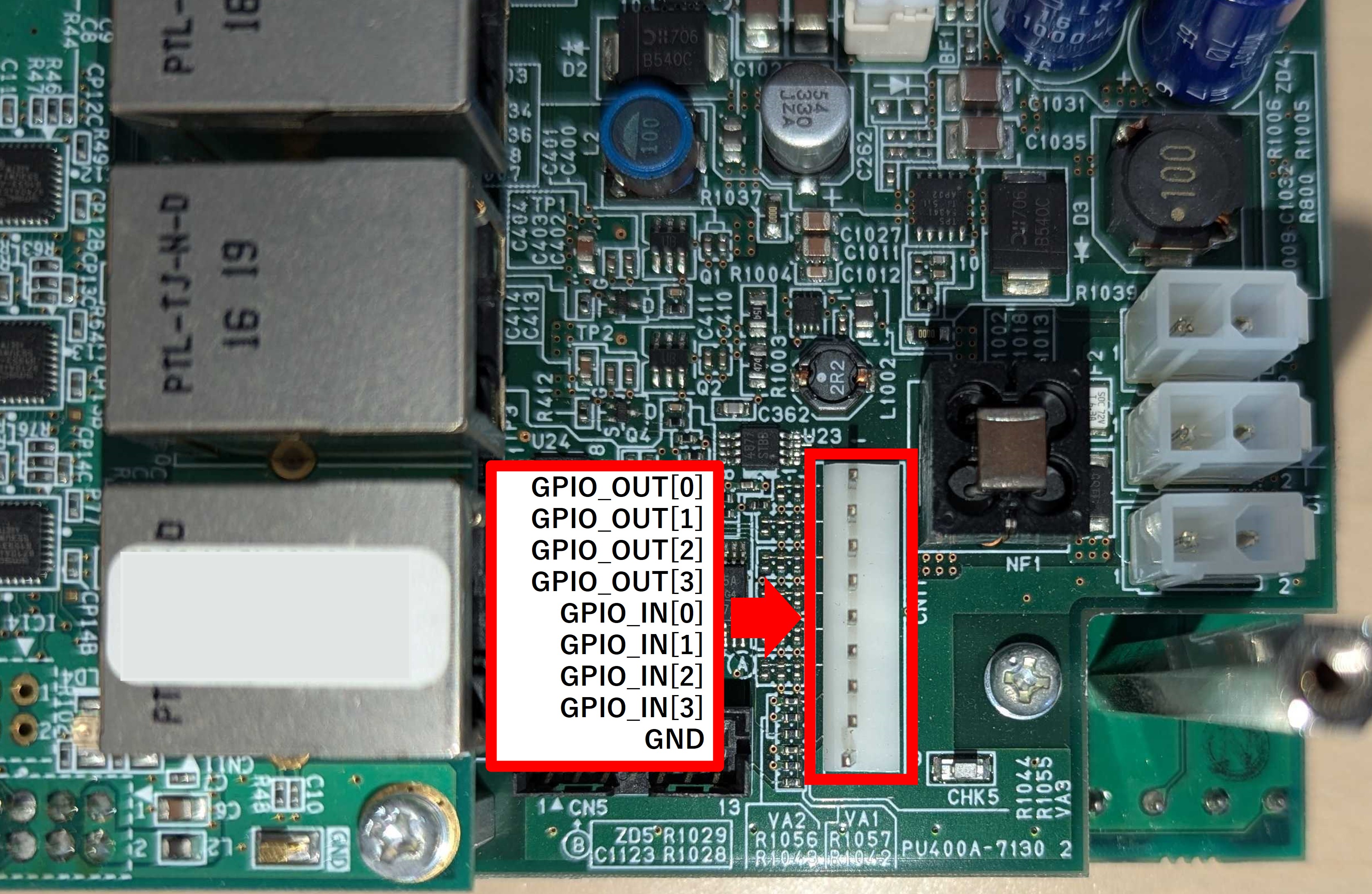
The signal output from each terminal (reference signal, temperature sensor, synchronization signal, PWM output, etc.) can be configured with SetGpioOut.
Each input terminal is active low.
The EmulateGpioIn command asserts each input from software.
The effective value the FPGA sees is the logical OR of the physical terminal and EmulateGpioIn.