AUTD3
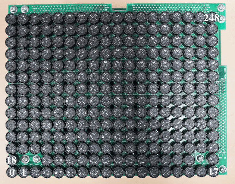
An AUTD3 device consists of 249 transducers per unit1. Each transducer is assigned the index shown below.
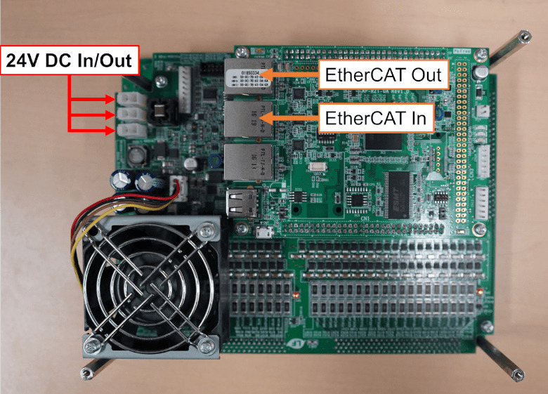
AUTD3 can be extended by connecting multiple units in a daisy chain, and the SDK can specify the phase / intensity of every transducer individually. When connecting multiple units, connect the PC to the EtherCAT In of the first AUTD3 (see the figure below), and then connect the EtherCAT Out of the n-th AUTD3 to the EtherCAT In of the (n+1)-th AUTD3.
Coordinate System
Section titled “Coordinate System”The coordinate system of AUTD3 is right-handed, and the center of the 0th transducer is the origin. The x axis is the long-axis direction, i.e. the 0 → 17 direction, and the y axis is the 0 → 18 direction. The unit of distance is mm.
Dimensions
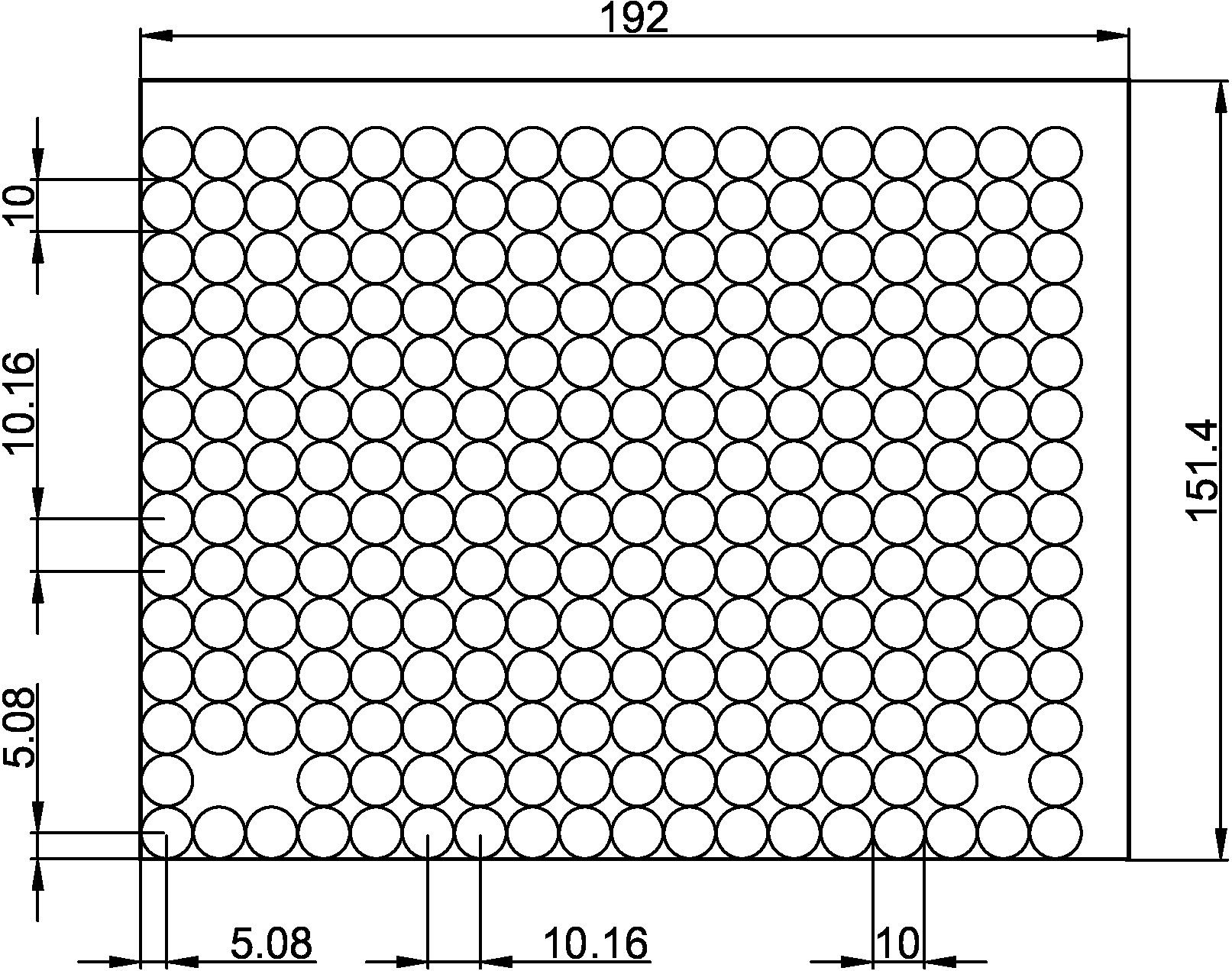
Section titled “Dimensions”The transducers are arranged at intervals of
Power Supply
Section titled “Power Supply”The AUTD3 power supply uses a
Footnotes
Section titled “Footnotes”-
Three transducers are removed from
for assembly. The screw holes were deliberately placed at these positions to make the gap as small as possible when multiple units are arranged side by side. ↩